



Mechanical ventilation is a cornerstone in the management of critically ill pediatric patients, ensuring adequate gas exchange and reducing the work of breathing. Its appropriate use requires a solid understanding of respiratory physiology, lung mechanics, and patient–ventilator interaction.
This article reviews the basic concepts of mechanical ventilation, including respiratory system anatomy and physiology, as well as key mechanical properties (compliance, resistance, and time constant) that determine respiratory dynamics. Ventilatory modes are classified according to control variable, breath sequence, and targeting scheme, facilitating their interpretation and clinical application.
Initial ventilator settings are described, emphasizing the importance of lung protective strategies. The article also addresses comprehensive monitoring, based on the systematic assessment of the patient, the ventilator, and the clinical response. Finally, the interpretation of ventilator waveforms is reviewed as a key tool for identifying asynchronies, changes in lung mechanics, and potential complications.
A thorough understanding of these principles is essential to optimize ventilatory support, improve clinical outcomes, and minimize ventilator-induced lung injury.
La ventilación mecánica es un pilar fundamental en el manejo del paciente crítico pediátrico, al permitir asegurar un adecuado intercambio gaseoso y reducir el trabajo respiratorio. Su aplicación requiere una comprensión sólida de la fisiología respiratoria, la mecánica pulmonar y la interacción paciente-ventilador.
Este artículo revisa los conceptos básicos de la ventilación mecánica, incluyendo la anatomía y fisiología del sistema respiratorio, así como las principales propiedades mecánicas (complianza, resistencia y constante de tiempo) que determinan la dinámica ventilatoria. Se describe la clasificación de los modos ventilatorios según la variable de control, la secuencia respiratoria y el esquema de control, facilitando la interpretación de la nomenclatura y su aplicación clínica.
Asimismo, se detallan los parámetros iniciales de programación, destacando la importancia de una ventilación protectora, y se aborda la monitorización integral del paciente basada en la evaluación sistemática del paciente, el ventilador y la respuesta clínica. Finalmente, se revisa la interpretación de las principales curvas del respirador como herramienta clave para detectar asincronías, cambios en la mecánica pulmonar y complicaciones.
El conocimiento de estos fundamentos es esencial para optimizar el soporte ventilatorio, mejorar los resultados clínicos y minimizar la lesión pulmonar inducida por ventilación mecánica.
Mechanical ventilation (MV) is a cornerstone of critical care in the pediatric intensive care unit (PICU). It allows for the partial or total replacement of respiratory muscle function, ensuring adequate oxygenation and proper elimination of carbon dioxide (CO2). It is estimated that up to 63% of patients admitted for acute respiratory or cardiorespiratory conditions require this type of respiratory support.1 Its implementation requires a thorough understanding of respiratory physiology, lung mechanics, and the complex interaction between the patient and the ventilator, which are key to optimizing effectiveness and minimizing potential complications of treatment.
The primary objective of mechanical ventilation is to maintain adequate gas exchange while minimizing ventilator-induced lung injury (VILI). International recommendations, in particular those from the Pediatric Acute Lung Injury Consensus Conference (PALICC-2), have emphasized the importance of physiology-guided ventilation, inspiratory pressure limitation, and the need for meticulous titration of ventilatory support in acute respiratory distress syndrome (ARDS).2–4
Anatomy and physiology of the respiratory systemUnderstanding the anatomy and physiology of the respiratory system is essential in order to understand invasive MV.
The alveoli are sac-like structures that remain open due to external pressures and the presence of pulmonary surfactant, which reduces their surface tension. When they collapse, relatively higher pressures are required to reopen them. This phenomenon underlies the physiological rationale for recruitment strategies and the need to deliver and titrate positive end-expiratory pressure (PEEP) in certain conditions. The lung parenchyma is composed of millions of interconnected alveoli, and together with the chest wall, they form a single system and determine respiratory mechanics.
At atmospheric pressure, an isolated lung would tend to collapse, but the negative pressure generated by the respiratory muscles and the structural support provided by the chest wall help maintain lung expansion by pulling outward. In infants and young children, the chest wall is more elastic due to the incomplete ossification of the rib cage. This results in weaker structural support, so the chest wall is more likely to collapse over the parenchyma, causing a drop in pulmonary volume and atelectasis.
Mechanical properties of the respiratory systemThe interplay of pressures acting through this alveolar-parenchymal-wall (pleural and alveolar) system is called transpulmonary pressure (TPP), and variations in TPP throughout the breathing cycle determine the degree of lung inflation and volume. At a TPP of +3 cmH2O, the lung is at residual volume only, requiring +5 cmH2O to stabilize at functional residual capacity and +30 cmH2O to reach the approximate total lung capacity.
During mechanical ventilation, positive airway pressure is delivered, reaching the alveoli and generating distending pressure from within, rather than through physiological means. The pressure required to achieve the TPP that brings the lung to the desired volume is delivered at the alveolar level.
Several mechanical parameters are essential for understanding ventilatory dynamics:
Compliance (C) represents the relationship between changes in volume and changes in pressure, reflecting the distensibility of the lungs. A lung with low compliance is stiff and requires greater pressure to expand. In pediatric patients, normal compliance values are typically around 1–2 mL/kg/cmH2O, but they vary widely throughout childhood.5,6
Elastance (E) is the inverse of compliance and represents the lung’s tendency to recoil.
Resistance (R) refers to the resistance to air flow in the respiratory system. Air flow occurs when there is a pressure gradient between two points (according to the theory of communicating vessels), and it is inversely proportional to resistance. In children, resistance is strongly influenced by the diameter of the airways and the size of the endotracheal tube.
The time constant (τ) is the product of the compliance and the resistance and is a general indicator of how quickly the lung fills and empties.
A short time constant indicates a stiff lung with low resistance that fills and empties quickly. A long time constant indicates increased resistance or compliance, leading to slower emptying and potential air trapping.
Understanding these physiological properties is essential for interpreting ventilator waveforms, recognizing changes in lung mechanics, and adapting ventilatory support to the clinical condition at hand.5
Classification of ventilation modes. TaxonomyThe available ventilation modes can be classified using a structured taxonomy based on three main components: the ventilator breath control variable, the breath sequence, and the targeting scheme. This method, proposed by Chatburn, allows a descriptive and unified nomenclature of the different modes that are commercially available at present,7,8 facilitating their understanding and comparison.
First of all, the control variable indicates whether the ventilator mainly regulates the pressure or the volume it delivers. In pressure-controlled (PC) ventilation, the ventilator sets and maintains the inspiratory pressure throughout the inspiration, resulting in a decelerating inspiratory flow. The delivered tidal volume depends on variables such as compliance, resistance, inspiratory time and the patient’s muscular effort. In volume-controlled (VC) ventilation, tidal volume and inspiratory flow are preset, and airway pressure varies according to lung mechanics (how the lungs receive the delivered volume). The plateau pressure, measured during the end inspiratory pause, allows an approximate calculation of the resulting alveolar pressure and provides information about compliance.
Secondly, the breath sequence determines whether breaths are mandatory (set frequency and inspiratory time), spontaneous (cycled by patient through triggering), or a combination thereof. Continuous mandatory ventilation (CMV) delivers breaths at a preset frequency, while continuous spontaneous ventilation (CSV) allows the patient to initiate and cycle breaths. Intermittent mandatory ventilation (IMV) modes combine mandatory and spontaneous breaths.
Last of all, targeting schemes are used to implement the defined objective of ventilation. There are set point (s) schemes, which deliver constant pressure or volume, and adaptive (a) schemes, that automatically adjust inspiratory pressure to achieve a target tidal volume. It is important to note that, although these adaptive modes may seem, based on commonplace commercial terminology, to be volume-controlled, at the physiological level they operate as PC modes, adjusting the delivered pressure based on the feedback the ventilator receives regarding the volume delivered in previous breaths.
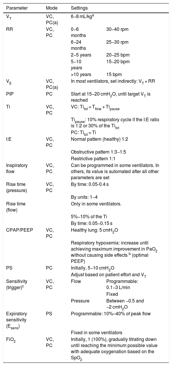
The initial programming of VM depends on the mode used, the type of patient, and the clinical condition.9 Before connecting the patient to the ventilator, it is crucial to ensure that it is properly calibrated and verify that it is functioning correctly using a test lung.
Mechanical ventilation requires setting the control variable (volume, pressure), the ventilatory sequence (CMV, IMV, continuous spontaneous ventilation), and the ventilatory parameters.
Initial ventilatory parameters- 1.
Breath control variable (Table 1)
Table 1.Initial ventilator settings.
Parameter Mode Settings VT VC, PC(a) 6−8 mL/kga RR VC, PC 0−6 months 30−40 rpm 6−24 months 25−30 rpm 2−5 years 20−25 bpm 5−10 years 15−20 bpm >10 years 15 bpm VE VC, PC(a) In most ventilators, set indirectly: VT × RR PIP PC Start at 15−20 cmH2O, until target VT is reached Ti VC, PC VC: Titot = Tflow + Tipause Tipause: 10% respiratory cycle if the I:E ratio is 1:2 or 30% of the Titot PC: Titot = Ti I:E VC, PC Normal pattern (healthy) 1:2 Obstructive pattern 1:3−1:5 Restrictive pattern 1:1 Inspiratory flow VC, PC Can be programmed in some ventilators. In others, its value is automated after all other parameters are set Rise time (pressure) VC, PC By time: 0.05-0.4 s By units: 1−4 Rise time (flow) Only in some ventilators. 5%−10% of the Ti By time: 0.05−0.15 s CPAP/PEEP VC, PC Healthy lung: 5 cmH2O Respiratory hypoxemia: increase until achieving maximum improvement in PaO2 without causing side effects b (optimal PEEP) PS PC Initially, 5−10 cmH2O Adjust based on patient effort and VT Sensitivity (trigger)c VC, PC Flow Programmable: 0.1−3 L/min Fixed Pressure Between −0.5 and −2 cmH2O Expiratory sensitivity (Esens) PS Programmable: 10%–40% of peak flow Fixed in some ventilators FiO2 VC, PC Initially, 1 (100%), gradually titrating down until reaching the minimum possible value with adequate oxygenation based on the SpO2 Abbreviations: bpm, breaths per minute; CPAP, continuous positive airway pressure; FiO2, fraction of inspired oxygen; PaO2, partial pressure of oxygen; PC, pressure-controlled mode; PC(a), pressure-controlled mode with adaptive targeting scheme; PEEP, positive end-expiratory pressure; PIP, peak inspiratory pressure; PS, pressure support; RR, respiratory rate; Tflow, inspiratory flow time; Ti, inspiratory time; Tipause, inspiratory pause time during which the gas is distributed throughout the alveoli and there is zero flow; Titot, total inspiratory time; VC, volume-controlled mode; VE, minute volume.
- 2.
Breath sequence
If no mandatory breaths are allowed, it is CSV.
If no spontaneous breaths are allowed, it is CMV.
If both spontaneous and mandatory breaths are allowed, it is IMV.
- 3.
Tidal volume (VT)
Amount of gas the ventilator delivers with each breath. Initially, it is standard practice to set it to 6−8 mL/kg.2,10
- 4.
Respiratory rate (RR), also known as breathing frequency (f).
Number of breaths per minute; depends on the age of the patient.
- 5.
Minute volume (VE)
Volume of gas administered per minute of ventilation. It is obtained by multiplying the VT by the RR and indicative of CO2 clearance. In most ventilators, the VE is set from the VT and RR.
- 6.
Peak inspiratory pressure (PIP)
Maximum airway pressure when gas is delivered during inspiration.
The initial PIP is usually set to 15–20 cmH2O, and subsequently adjusted until reaching an adequate VT.
- 7.
Inspiratory time (Ti)
The period of time in which gas enters the airways, including its distribution in the lungs.
In VC, the total inspiratory time (Titot) is subdivided into the dynamic inspiratory (Tidyn), during which gas is delivered, and the inspiratory pause time (Tipause). The Tipause can be programmed as a percentage of the total cycle time (10% if the inspiratory-to-expiratory ratio is is 1:2) or a percentage of the Titot (30%).
In PC, the Tipause is not programmed, as gas is delivered throughout the entire Ti unless the applied pressure and the pressure in the lungs equilibrate.
- 8.
Inspiratory-to-expiratory ratio (I:E)
An expression of the proportions of time dedicated to inspiration and expiration in each ventilation cycle. Typically, the inspiratory and expiratory times are adjusted so that expiration lasts twice as long as inspiration (I:E of 1:2).
- 9.
Inspiratory flow (flow rate)
Rate at which the gas enters the airway.
- 10.
Pressure rise time and inspiratory flow rise time
Pressure rise time: time it takes the airway pressure to reach the set inspiratory pressure.
Flow rise time: this feature is only available in some ventilators. It is the time to reaching the peak flow rate.
- 11.
Continuous positive airway pressure (CPAP)–PEEP
CPAP stands for continuous positive airway pressure during inspiration and expiration. It is used in spontaneous ventilation modes. It prevents alveolar collapse and improves oxygenation.
Both (CPAP and PEEP) deliver positive pressure, CPAP throughout the breathing cycle and PEEP only during expiration. The initial pressure in PEEP is set at approximately 5 cmH2O in patients without pulmonary disease. In the case of hypoxemia of a respiratory etiology, this setting should be increased.
- 12.
Pressure support
Delivery of pressure to support spontaneous breathing. It is programmed with a constant value, independent of the patient’s respiratory effort.
It compensates for the increase in work of breathing caused by the endotracheal tube in spontaneous breaths, in addition to the additional pressure required to increase the VT.
- 13.
Sensitivity (trigger)
Threshold set to open the inspiratory valve in response to a patient’s signal. It must be programmed in assisted, supported, or spontaneous breaths.
It should be sufficiently sensitive to detect patient effort while avoiding autotriggering.
The breath can be triggered in two ways:
- •
Flow triggering: patient effort causes negative flow in the circuit that is detected by the sensor and triggers the opening of the inspiratory valve. This type requires less patient effort, as a small volume of air opens the valve.
- •
Pressure triggering: patient effort generates a negative pressure that is detected and triggers the opening of the valve. It usually requires greater patient effort compared to flow triggering (it requires a drop of pressure below the PEEP through isometric muscle contractions that do not achieve air flow).
In newborns, in whom the effort required may be excessive, constant flow ventilators are frequently used, as they let the infant breathe without difficulty throughout the respiratory cycle.
- 14.
End-inspiration (regulation of expiratory sensitivity or Esens)
Percentage decrease in peak inspiratory flow to end inspiration and begin expiration. This is programmed only in pressure support mode. Some ventilators have this setting preset so that it cannot be adjusted.
- 15.
Fraction of inspired oxygen (FiO2)
Percentage of oxygen (O2) in the gas mixture delivered by the ventilator, which can range from normal room air (FiO2 of 0.21) to pure oxygen (FiO2 of 1). The goal, given the toxicity of O2, is to ventilate the patient at the lowest possible FiO2, ideally below 0.6.
- 16.
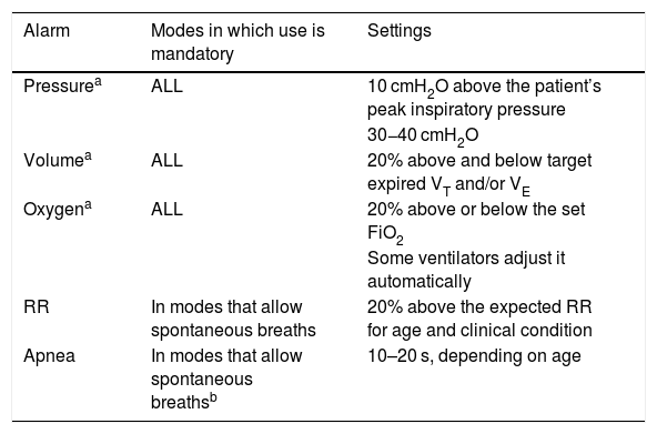
Alarms (Table 2)
Table 2.Alarms.
Alarm Modes in which use is mandatory Settings Pressurea ALL 10 cmH2O above the patient’s peak inspiratory pressure 30−40 cmH2O Volumea ALL 20% above and below target expired VT and/or VE Oxygena ALL 20% above or below the set FiO2 Some ventilators adjust it automatically RR In modes that allow spontaneous breaths 20% above the expected RR for age and clinical condition Apnea In modes that allow spontaneous breathsb 10–20 s, depending on age Abbreviations: FiO2, fraction of inspired oxygen; RR, respiratory rate; VE, minute volume; VT, tidal volume.
Alarms are visual and audio signals that must be programmed in the system to alert of changes in output parameters, programming errors, system malfunctions, changes in the patient’s condition, or patient–ventilator asynchrony.
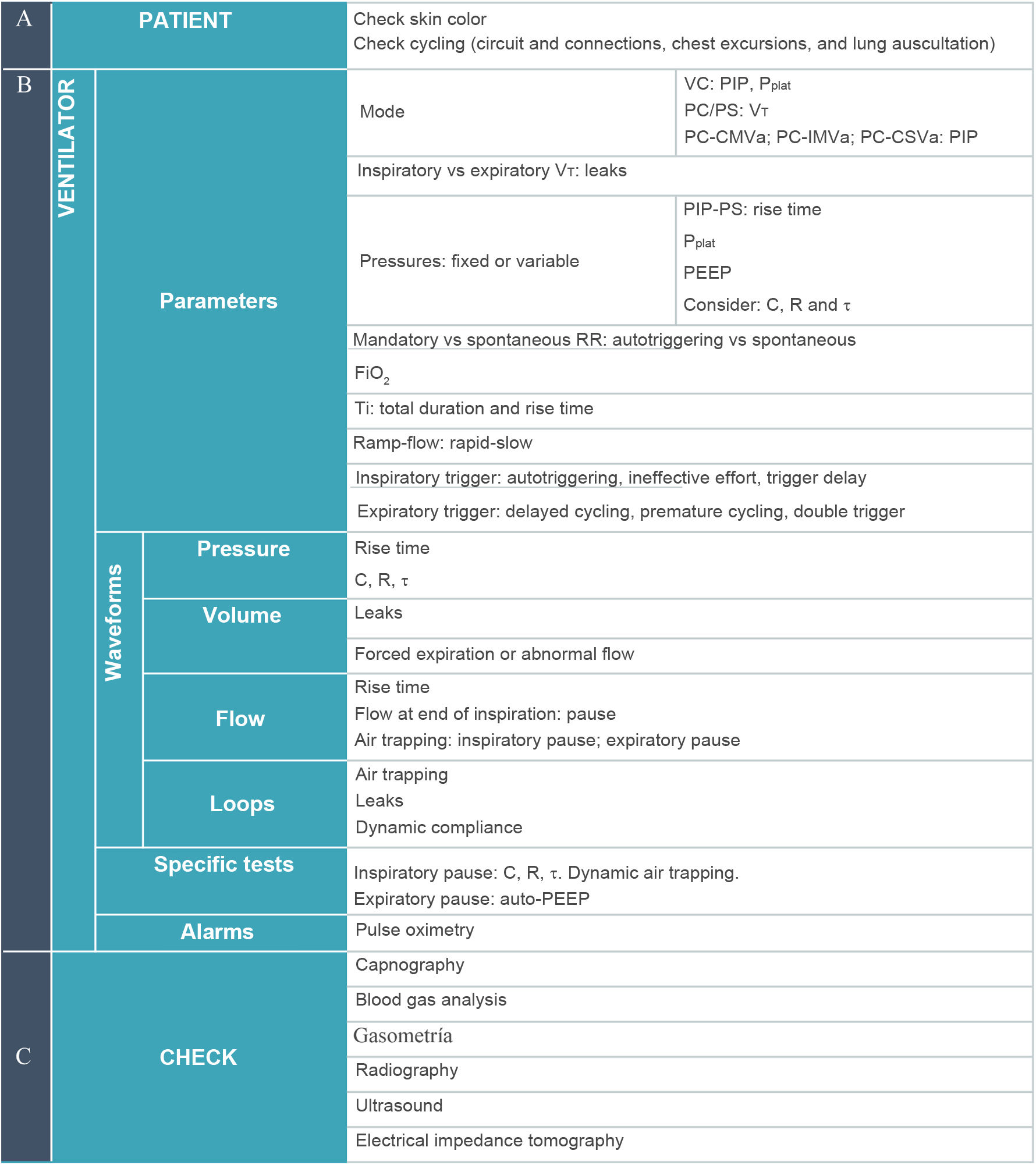
Respiratory monitoringTable 311 outlines a systematic approach to patient–ventilator assessment for respiratory monitoring that should be implemented in any mechanically ventilated patient.12,13 It follows an ABC sequence, so it should be performed in the order presented:
- A.
Patient (airway/assessment). Examination of the patient: inspection, palpation, skin color, auscultation, etc. It is the first step in the assessment and can never be replaced by any other data, graphical or numerical.
- B.
Ventilator (breathing). The second step is to assess all the information contributed by the ventilator:
- 1.
Mode: check which mode is being used to identify the control and cycling variables as well as the targeting scheme.
- 2.
Numerical data, to be checked in the following order:
- a.
Dependent variable: must be identified in each mode.
- -
VT in PC-CMV or PC-CSV (pressure-controlled CMV or CSV with a set-point targeting scheme).
- -
Peak pressure in VC-CMVs, PC-CMVa or PC-CSVa (volume-controlled CMV with set-point targeting scheme, pressure-controlled CMV with an adaptive targeting scheme, or pressure-controlled CSV with an adaptive targeting scheme).
- -
- b.
Pressures: PIP in volume-controlled modes and pressure-controlled modes with an adaptive targeting scheme. Plateau pressure (Pplat) in volume-controlled modes, in addition to checking PEEP. Analyzing the pressures will provide insight into whether they are appropriate for the specific mechanically ventilated patient. If the pressures are high, the operator should assess whether this is consistent with the patient’s condition or it may be due to some problem. In volume-controlled mode, this can be determined by the difference between the PIP and the Pplat. If the pressures are abnormally low, extubation or leaks should be suspected.
- c.
RR. The values to be considered are its absolute value (whether it is high or low) and the difference between the set rate and the rate that is actually observed in order to identify potential autotriggering or spontaneous breaths.
- d.
FiO2. Most modern ventilators have integrated mechanisms to monitor inspired oxygen, but some (such as transport ventilators or noninvasive ventilation devices) do not, in which case the delivered FiO2 is calculated.
- e.
VT. Consider the difference between the inspiratory and the expiratory VT (detection of air leaks) and whether these two values are adequate for the specific patient (particularly in relation to pressure control).
- f.
Diagnosis of asynchrony. The parameters that must be evaluated together are: Ti, flow or pressure rise time, inspiratory trigger, and expiratory trigger. A combined analysis of these parameters, supported by the inspection of waveforms, allows for an initial assessment of asynchrony. Autotriggering is the cause of asynchrony that can be identified earliest, as it can be suspected as soon as the difference between the programmed RR and the actual RR is identified.
- a.
- 3
Waveforms: their inspection adds to the information obtained by analyzing the numerical data. Some complications can be diagnosed through waveforms or with special procedures. The most important waveform is the flow-time curve. The aspects to assess in inspecting this waveform are:
- a.
Whether air has been effectively delivered during the Ti. In PC modes, check for the presence of a zero-flow phase at the end of inspiration.
- b.
Whether the lungs have completely emptied during expiration. This is verified by checking whether there is a zero-flow phase at the end of expiration, which rules out dynamic air trapping.
- a.
- 4.
Special tests: They provide more detailed information about the characteristics of the respiratory system (compliance, resistance, and time constant) and are used to assess for air trapping.
- 5.
Alarms: They must be reset once it has been verified that all the data provided by the patient and the ventilator appear to be correct for the patient's clinical condition.
- 1.
- C.
Monitoring (circulation/control): the data available through monitoring (pulse oximetry, end-tidal or transcutaneous capnometry, blood gas analysis, and imaging tests) is considered to determine whether the outcomes of VM are appropriate based on its goals. If not, the settings should be adjusted and the patient–ventilator assessment performed again from the beginning.
Systematic approach to respiratory monitoring in mechanically ventilated patients, specifying the different parameters to consider in (A) pAtient Assessment, (B) ventilator/Breathing and (C) checking cardiovascular monitoring, laboratory and imaging test data. This is important both for programming the initial settings and when there are changes in clinical condition or ventilator settings.
Abbreviations: C, compliance; FiO2, fraction of inspired oxygen; PC, pressure control ventilation; PC-CMVa, pressure control continuous mandatory ventilation with adaptive targeting scheme; PC-CSVa, pressure control continuous spontaneous ventilation (pressure support) with adaptive targeting scheme; PC-IMVa, pressure control intermittent mandatory ventilation with adaptive targeting scheme; PEEP, positive end-expiratory pressure; PIP, peak inspiratory pressure; Pplat, plateau pressure; PS, pressure support; R, resistance; RR, respiratory rate; Ti, inspiratory time; τ, time constant; VC, volume control; VT, tidal volume.
Assessments should be repeated frequently at regular intervals or following changes in clinical condition or ventilator settings, always following the ABC framework detailed above.
To assess the oxygenation status of a patient, it is important to differentiate two relevant aspects: the efficiency of the gas exchange process (assessed by means of the ratio of the partial pressure of arterial oxygen [PaO2] and the FiO2 [P/F] or, if not possible, of the peripheral oxygen saturation [SpO2] and the FiO2 [S/F]) and blood oxygen levels (assessed by means of the PaO2 or, if not available, the SpO2).
In the case of acute hypoxemic respiratory failure, the severity of hypoxemia and the shunt should be assessed by means of the PaO2 and P/F (or, if not available, SpO2 and S/F). Subsequently, the etiology should be assessed, and the shunt identified, to provide treatment appropriate to the particular situation.14,15
Monitoring capnography and capnometry values is a must in intubated individuals and is considered a standard of care in the management of critically ill patients.16,17
Analysis of the main ventilator waveforms (Figs. 1 and 2)Flow–time curveIt illustrates changes in gas flow in the airway during the respiratory cycle (Figs. 1 and 2).
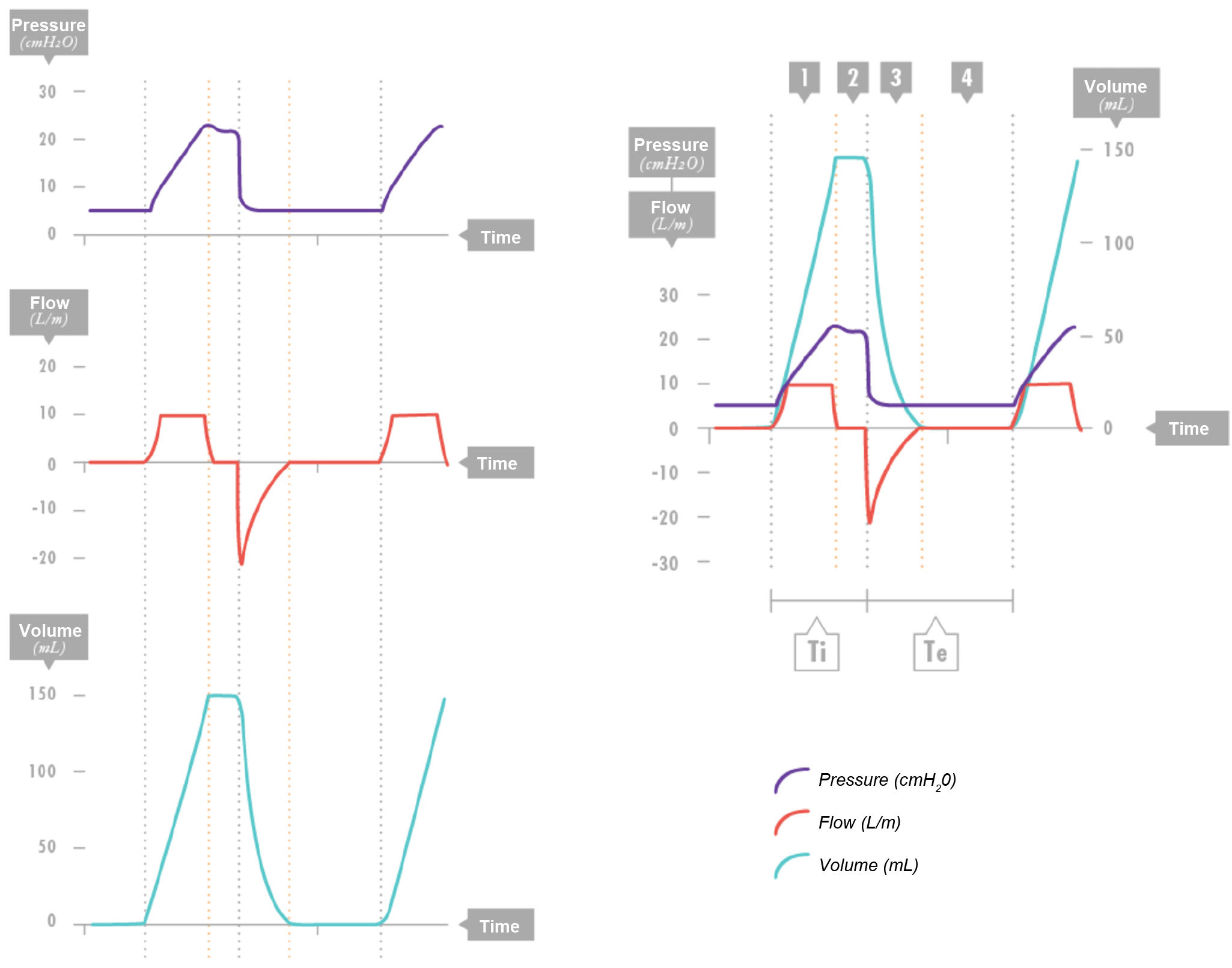
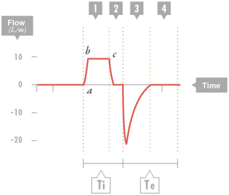
The typical pattern of the flow-time scalar in volume-controlled mode is a square-shaped waveform, as the flow is rapid and remains nearly constant (Fig. 3). There is an initial rise phase followed by a constant-flow phase (inspiratory time and flow). This is followed by a pause (the inspiratory and expiratory valves remain closed).

Volume control. Combined view of the three waveforms. Segment 1: Inspiratory phase with constant flow: constant inflow with a progressive increase in pressure and volume gain. Segment 2: Pause. No air enters or exits (zero flow). The pressure drops to a plateau value, and the volume remains constant. Segment 3: Expiration. Volume exits and pressure drops to the positive end-expiratory pressure (PEEP) level, with negative expiratory flow. Segment 4: Zero-flow expiratory phase (it is important that there be sufficient time for the inhaled air to be exhaled); the PEEP and volume remain constant.
Te: expiratory time; Ti, inspiratory time.

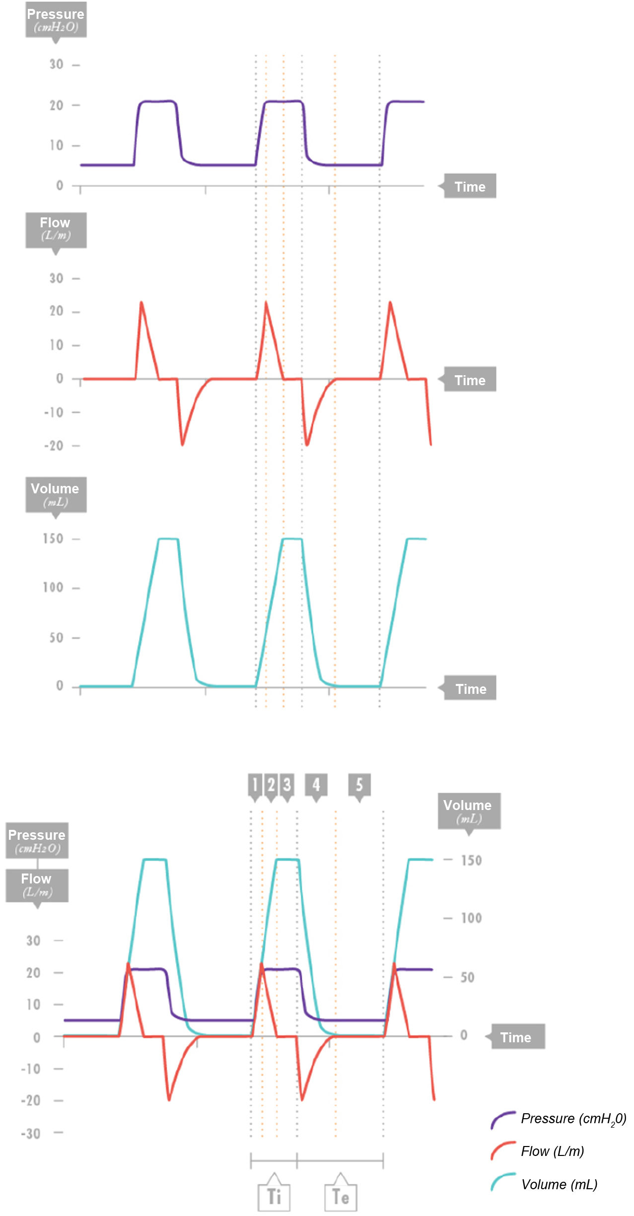
Pressure control. Combined view of the three waveforms. Segment 1: Segment 1: delivery of peak inspiratory flow achieving a specific pressure. Segment 2: The flow decelerates while maintaining a nearly constant pressure in the system. Segment 3: Once the pressures of the ventilator and the lungs equilibrate, gas no longer enters the lungs, so the flow is 0. This is not considered a programmed pause. Segment 4: Effective expiration. Volume is expired, pressure drops to the positive end-expiratory pressure (PEEP) level, and negative expiratory flow occurs. Segment 5: Zero-flow phase at end of expiration (it is important that there be sufficient time for the inspired air to be exhaled); there are no changes in PEEP or volume.
Te: expiratory time; Ti, inspiratory time.

Volume control. Flow-time curve. Segment 1: consists of two parts: the first (a–b), in which there is a rapid increase in inspiratory flow until the set flow is reached, which then remains constant (b–c). Segment 2: pause or zero-flow period, during which flow drops sharply and both valves (inspiratory and expiratory) are closed. Segment 3: effective expiration. Segment 4: zero-flow time at the end of expiration (it is important that sufficient time is allowed for the inhaled air to be exhaled). These segments may change in situations where there is obstruction to air flow (bronchospasm, mucus, kinking, etc.). The time constant can be estimated by dividing the effective expiratory phase (a–c) by 5.
Te: expiratory time; Ti, inspiratory time.
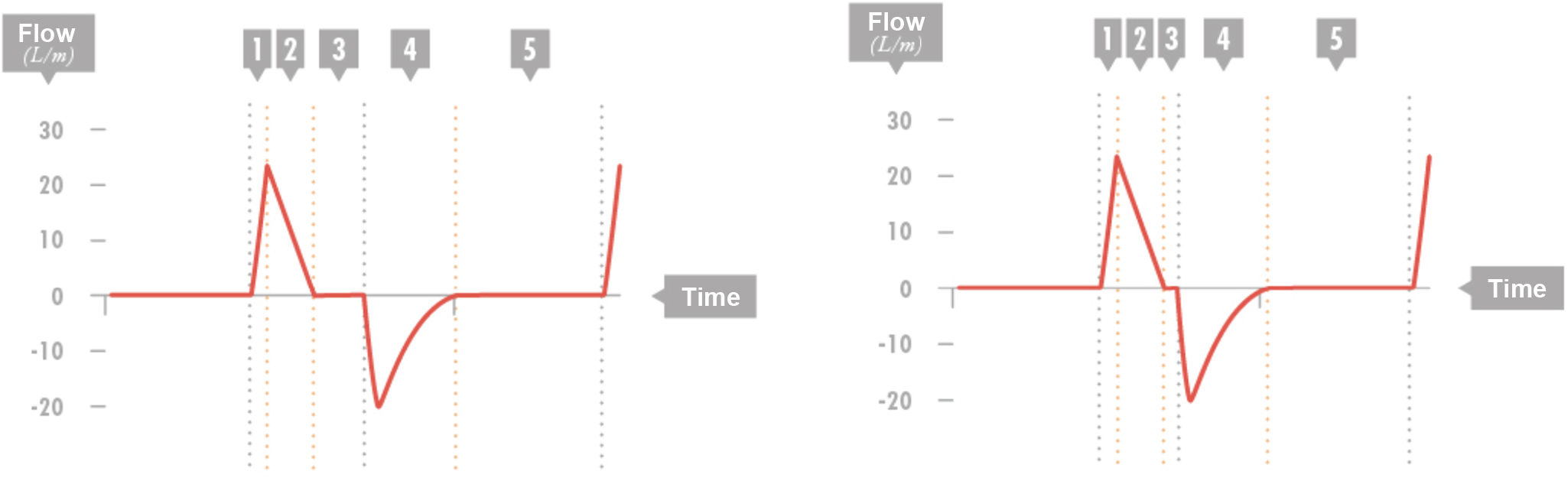
In pressure-controlled modes, this is a very important waveform. It shows a decelerating pattern with a high initial flow rate that decreases until the target pressure set on the ventilator is reached in the lungs, when the flow rate is 0 if the pressures equilibrate and no gas is entering or leaving the airway (Fig. 4).

Pressure control. Flow-time curve. Segment 1: Inspiratory flow peak. Segment 2: Decelerating inspiratory flow. Segment 3: Zero flow. This pause is not preset. If there is not at least a minimum amount of time at zero flow, it is not certain whether the pressure contributes to the tidal volume. Segment 4: Effective expiratory flow. Segment 5: Zero flow at the end of expiration.
When the inspiratory time is insufficient, the zero-flow segment may be shorter or even disappear entirely, a situation typical of cases with a prolonged time constant (obstructive pattern). It seems logical to assume that in pressure-controlled mandatory breath cycles, the inspiratory time must be long enough for the descending curve to reach zero.
In both cases, expiration is a passive phase. The magnitude, duration and pattern of the waveform are determined by the compliance and the resistances of the airway and the patient circuit (length and size of tracheal tube), with a segment of time of effective expiration and a segment of time with zero flow. The τ of the patient can be calculated from this curve. To be able to do this, it is important to verify that there is a zero-flow segment. The effective expiratory time is obtained by measuring the time elapsed until reaching zero flow. This time is equivalent to 5τ, so τ can be calculated by dividing it by 5.
Volume–time curveThe ventilator calculates and displays the volume entering or leaving the lungs based on the inspiratory or expiratory flow and the duration of each.
The expiratory and inspiratory limbs must have the same magnitude, if the expiratory volume is greater (additional gases, such as nitric oxide) or smaller (air leak, air trapping), the shape of this curve will change. The difficulty in exhaling previously inspired air will result in a less-steep descending limb (flattening) compared to the inspiratory limb.
In VC modes, there must be a moment in which there is no volume change that may not occur in PC modes, in which the volume is at the target value.
Pressure–time curveIt represents the pressure changes measured in the ventilator over time.
In VC modes, it offers very valuable information. There are three distinct phases: (1) an increasing phase until the pressure peaks, corresponding to the part of the cycle in which air is entering the airway; (2) Pplat at zero flow, whose value depends on the distribution of the air that has previously entered the lungs, and (3) expiratory phase during which PEEP can be programmed.
The Pplat results from the intrapulmonary gas volume and, since it occurs at zero flow, reflects chest wall and lung compliance. However, in phase 1, the PIP results from 2 components: the resistive pressure, involving the resistance (of the airway and circuit) to the flow or passage of air that needs to be overcome, and the pressure exerted by this air on the lung (chest wall and lung compliance). Therefore, the difference between the PIP and the Pplat serves as a diagnostic tool, as it provides information about the mechanical properties of the lung, allowing for differentiation between obstructive and restrictive patterns.
In PC modes, this is the waveform that provides the least information to the clinician and remains virtually constant regardless of patient characteristics. The shape of the pressure waveform in this mode is typically square.
Key points- 1.
Mechanical ventilation must ensure adequate gas exchange while minimizing the risk of VILI and adapting to the patient’s physiology.
- 2.
The correct interpretation of respiratory mechanics (compliance, resistance, and TPP) is essential for adequate adjustment of ventilatory parameters.
- 3.
Safe initial settings include a tidal volume of 6–8 mL/kg and a PEEP set according to the clinical situation.
- 4.
Systematic respiratory monitoring (ABC patient–ventilator assessment) allows early detection of complications, asynchrony, or the need of adjustments.
- 5.
To assess the oxygenation status of a patient, it is important to differentiate two relevant aspects: gas exchange (assessed by means of the P/F or, if not available, the S/F) and blood oxygen levels (assessed by means of the PaO2 or, if not available, the SpO2).
- 6.
Monitoring capnography and capnometry values is a must in intubated individuals and considered a standard of care in the management of critically ill patients.
The authors declare that no generative AI or AI-assisted technologies were used in the writing, analysis, or preparation of this manuscript.
FundingThis research project did not receive specific financial support from funding agencies in the public, private or not-for-profit sectors.
The authors have no conflicts of interest to declare.